
Interactive · 9 questions
Resistors
So-called "ohmic conductors" are circuit elements (components) that have a constant resistance, even as the current through it varies. We usually simply refer to this idealisation as a "resistor", which is characterised by its single-valued resistance Here refers to the potential difference across and the current through the component. Recall that while this definition of resistance applies to any component, only when the resistance is independent of and do we refer to the component as a "resistor".
[The adjective "ohmic" is meant to invoke Ohm's law, which is the empirical finding that the potential difference across the resistor is proportional to the current flowing through it. Ohm's law is less a law of nature than a way to characterise the relationship between and . (The status is similar to "Hooke's law" for springs.)]
Which of the following is not necessarily true about a "resistor"?
Common-sense (but inaccurate) ideas about electricity
There are several common-sense ideas about electricity that can potentially lead to conceptual difficulties. I mention a few of these here, so you are particularly aware of possible pitfalls, if you currently subscribe to some of these ideas. If this is indeed the case, I've provided a brief discussion about why these ideas should be reconsidered, and you should certainly think more about them throughout the rest of this lesson. (I'll try to test for some of these in questions later, to help you identify if they are relevant for you.)
[This list is selected from the educational research literature, but I have not been able to access several of the original texts to provide the proper attribution. One nice secondary source I found was KÜÇÜKÖZER, Hüseyin; KOCAKÜLAH, Sabri. Journal of Turkish Science Education 4.1 (May 2007): 101-115. See also the Furry Elephant website.]
1. Battery as a constant current source
One common misconception is that batteries provide a constant supply of current. For example, if I connect this battery up in a circuit, it always provides 1 A of current, regardless of the actual circuit. (What is more accurate is actually that batteries are typically constant voltage sources, so the potential difference across its terminals is independent of the actual circuit. This is slightly modified in a more sophisticated model of a battery with internal resistance, but let's defer this discussion.)
2. Current is consumed as it flows around the circuit
This is another example of not having clear concepts to differentiate between the ideas of potential (voltage), current, and even energy. Generally, we should think of current like a flow of fluid, so it does not really get "used up". It is the electrical potential that tends to change in going around a circuit. This change is also related to the change of electrical energy to other forms (e.g. heat in a resistor).
3. "Upstream" changes in a circuit can affect "downstream" but not vice versa
For example, people might think that adding a resistor on one side of a bulb (but not on the other side) might affect its brightness, if it's on the side nearer a particular end of the battery. (In reality, the circuit as a whole generally has to be taken into consideration, as the phenomenon of current flow is actually a collective behaviour/property of the system.)
If you suspect problems, clarify...
There are subtle problems that might plague understanding, so please make a note if you think you suffer from any of these. I quite enjoy the Furry Elephant website, which goes into quite a lot of depth about the use of analogies, language, teaching approaches, misconceptions and the like -- well worth taking a look if you want to explore further.
Basic Circuit Setup
The basic "anatomy" of the electrical circuits that we will be considering, for the most part, consists of a battery (direct current e.m.f. source) connected by ideal wires (that have zero resistance) to the two ends of a single resistor. This single resistor can be replaced by combinations of resistors that are wired together with an "effective resistance" across the two "ends".
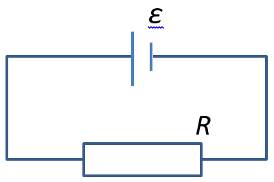
Basic circuit setup with battery and resistor (the current flows anti-clockwise in the diagram, since the positive terminal of the battery is represented by the longer line)
What is the potential difference across the resistor in the diagram above, and what is the current through it?
What is the current through the battery?
If the resistor is replaced with one that has double the resistance, what is the potential difference across this new resistor?
If the resistor is completely removed, and the ends of the wire are kept apart, what is the potential difference across the ends of the wire?
Adding branches
Now imagine the circuit diagram shown below, where we have included an additional resistor, and called the resistors and respectively.
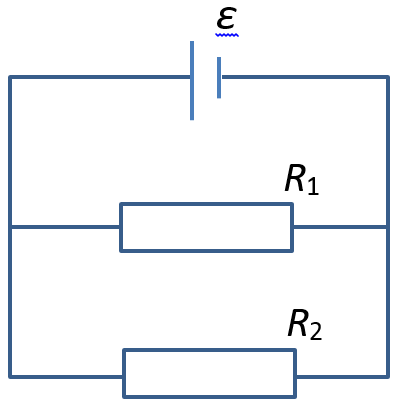
Circuit setup with two resistors "in parallel".
If the resistance , how does the potential difference across compare with the potential difference across ?
Possible misconception
Are you convinced that, for the circuit you just saw, the potential difference across each resistor is the same? This is an important point, which allows us to derive conclusions about current flow and the "effective resistance" of the combination of resistors.
Did the battery "provide" more current when the second resistor was "added"?
Battery characteristics
How did the battery produce "extra" current when an additional resistor is added? What happens to conservation of charge? What about conservation of energy?
Is "charge conservation" violated in this example?
Is "energy conservation" violated in this example?
Resistors in parallel
When more than one resistor is added in a circuit, like and , such that the potential difference across each resistor is the same, we describe this as a "parallel" arrangement of resistors. This is analogous to adding more lanes on an expressway.
We can use the observation that the potential difference is constant to calculate the current through each resistor. The total current through the battery will be the sum of the currents through each resistor, since this is how the network is connected up. The analogy is that when lanes merge on the expressway, the vehicles must move faster when there are less lanes, so as not to cause congestion.
The current through is and so the total current is which means that the effective resistance of the parallel arrangement of and is given by
This formula for the effective resistance can obviously be generalised to an arbitrary number of resistors in parallel.
Resistors in series
Come up with formula and end package...