
Interactive · 5 questions
Suppose we have a circuit like that shown in Figure 1. There are 2 resistors, called and .
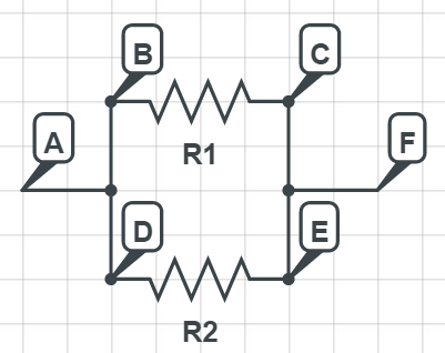
Figure 1: Badly drawn circuit
For the rest of this "lecture," I will denote as the potential difference between points and . (Of course, it really should be written as , but takes 6 characters to write in , so it'll save me work. Remember that whenever you see , it really means .)
Remember that, in any circuit that we consider in physics problems, the wires are ideal (unless otherwise stated), which means that the resistance, and hence voltage difference, is 0.
How does compare to ?
Using similar reasoning, we get that . Hence, . Thus, for any resistors connected in parallel, the voltage drop across each of them is the same. (We'll define parallel more rigorously in a later "lecture.")
Now, assume all resistors obey Ohm's law. For simplicity, let .
What is the current that flows between and ?
Now, what is the current that flows between and ?
Let be the unlabeled node between and . What is the current that flows between and ?
Now, if you go and review the "lecture" on resistors in series, you'll find that there was an explanation about equivalent resistance.
So, what is the equivalent resistance of and ?
We can easily extend this argument to show that the equivalent resistance for resistors in parallel is just .
That's it for now. Later we will explore more complicated circuits and do a few examples. We will have to use both series and parallel equivalent resistance formulas to bring together a whole bunch of resistors together into one, then figure out the current, then expand the resistors one by one again using everything we have derived so far.